


SECTION 1: CORE FUNDAMENTALS & ENGINEERING ADVANTAGES OF RAISED PEDESTAL SYSTEMS
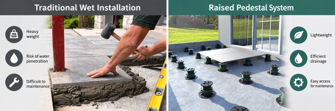
In contemporary landscape architecture, roof terrace engineering, commercial podiums, and public urban plazas, outdoor hardscaping is undergoing a massive shift from traditional wet-mortar screed installation to modular dry raised floor systems (Adjustable Pedestal Systems). Understanding the fundamental physics and lifecycle advantages of raised systems is essential for technical specification and project consulting.
Structural Load Advantages: 1. Extreme Dead-Load Reduction (>80% Weight Savings):
Conventional wet-screed bed installations (30–50mm sand/cement mortar plus leveling bed) impose a crippling dead load of 150–200 kg/m² onto roof slabs. For post-tensioned slabs, cantilevered balconies, and timber-framed developments, this excessive weight risks long-term structural deflection, cracking, and water pooling. A pedestal-supported raised system weighs a mere 15–25 kg/m² (including 20mm porcelain slabs), releasing critical building capacity.
Waterproofing Protection & Lifecycle Maintenance: 2. 100% Non-Destructive Cavity Inspection:
Wet-bonded tiles permanently seal the underlying waterproofing membrane. When building settlement causes leaks, tracing the water ingress point is notoriously difficult, necessitating destructive jackhammering of pristine stone. Raised pedestal flooring creates a service void where any tile can be lifted within 3 seconds using vacuum cups for zero-loss inspection of electrical cabling, drainage outlets, and membranes, and returned without trace.
Surface Drainage & Aesthetic Integrity: 3. Elimination of Efflorescence & Instant Stormwater Infiltration:
Soluble alkalis in mortar migrate upwards through porous grout, producing unsightly white efflorescence (calcium carbonate stains) and persistent puddles. Pedestals support slabs with 2–4mm open perimeter joints, allowing stormwater to drop instantly into the void below. Slabs remain permanently dry, slip-resistant, and free from efflorescence.
SECTION 2: COMPREHENSIVE PAVER/TILE LAYOUT & PEDESTAL SIZING MATRIX
Outdoor paving materials—predominantly 20mm vitrified porcelain pavers and 30–50mm calibrated natural granite—exhibit distinct flexural strengths and elastic deflection thresholds. Specifying the correct pedestal spacing and intermediate reinforcement is paramount to prevent punching shearing, corner breakage, and base collisions.
2.1 300 x 300 mm Format: The Physics of Base Overlap & Mandatory Mini-Pedestal Selection
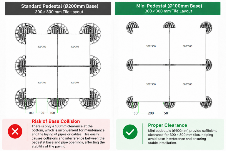
Critical Engineering Rule: 300 x 300 mm pavers are common on compact residential balconies and narrow perimeter pathways. For this specific dimension,
Mini Pedestals shall be specified.
1. Physical Collision of Standard Bases: Standard adjustable pedestals feature a wide base plate diameter of 190–210 mm (nominal 200 mm) to distribute weight over membranes. When pavers measure only 300 x 300 mm, the center-to-center axis distance between adjacent pedestals is exactly 300 mm. At 4-corner intersections, adjacent base radii (100 mm + 100 mm = 200 mm) leave a tight 100 mm clearance in theory. In actual construction, minor sub-base slope adjustments or perimeter cuts cause adjacent 200 mm bases to collide, overlap, and tilt, preventing pedestals from sitting plumb and causing severe paver rocking.
2. Mini-Pedestal Technical Superiority: Mini pedestals are engineered with a compact base diameter of 100–120 mm. Under a 300 mm grid, this provides 180–200 mm of clear separation between bases, eliminating collision risks entirely. Furthermore, Mini pedestals deliver an ultimate compressive load capacity exceeding 800 kg (8 kN), accommodate ultra-low cavity heights (10–25 mm / 19–30 mm), and reduce unit costs, saving 30–50% on small-format budgets.
2.2 400 x 400 mm & 450 x 450 mm Formats: Standard 4-Corner Point Support
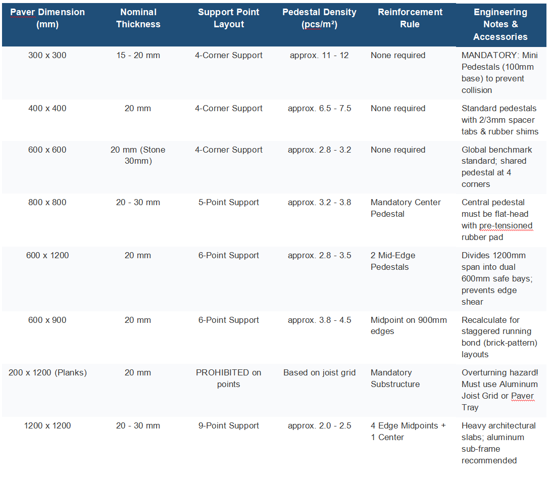
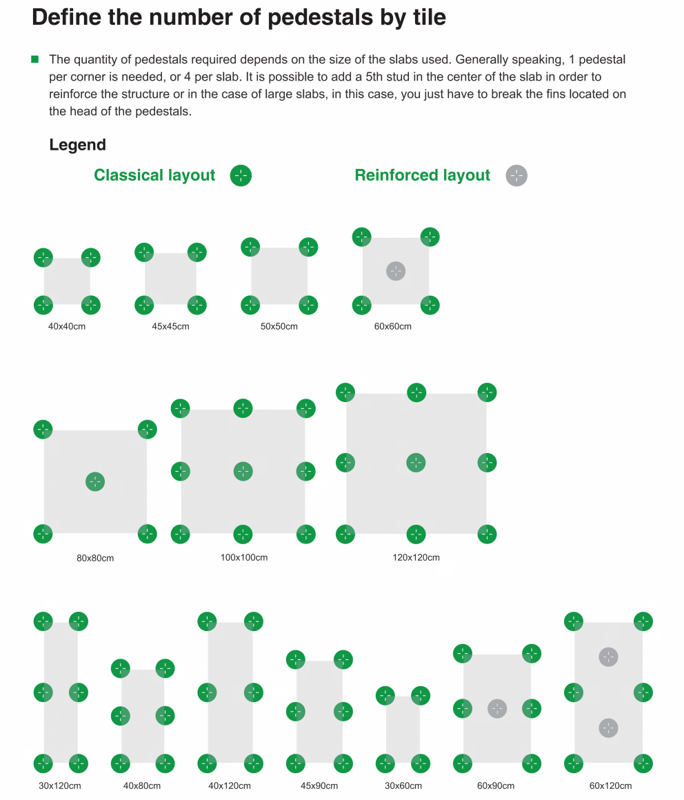
4-Corner Point Support. Each paver corner rests on one quadrant of a pedestal head fitted with spacer tabs. Pedestals are shared among four adjacent slabs. Typical consumption is 6.5–7.5 units/m². Flexural spans remain well within the safety threshold of 20mm porcelain, requiring no central reinforcement.
2.3 600 x 600 mm Format: The Global Benchmark Specification
Representing over 65% of international commercial and residential specifications. Supported at all 4 corners with shared pedestals. Standard consumption: 2.8–3.2 units/m².
20mm vitrified porcelain paver (breaking strength > 10,000 N, EN 1339) or 30–50mm calibrated natural stone. Rubber acoustic shims must be placed on pedestal heads to eliminate micro-tolerances and eliminate walking clatter.
2.4 800 x 800 mm Format: Mandatory 5-Point Support Protocol (4 Corners + 1 Center)
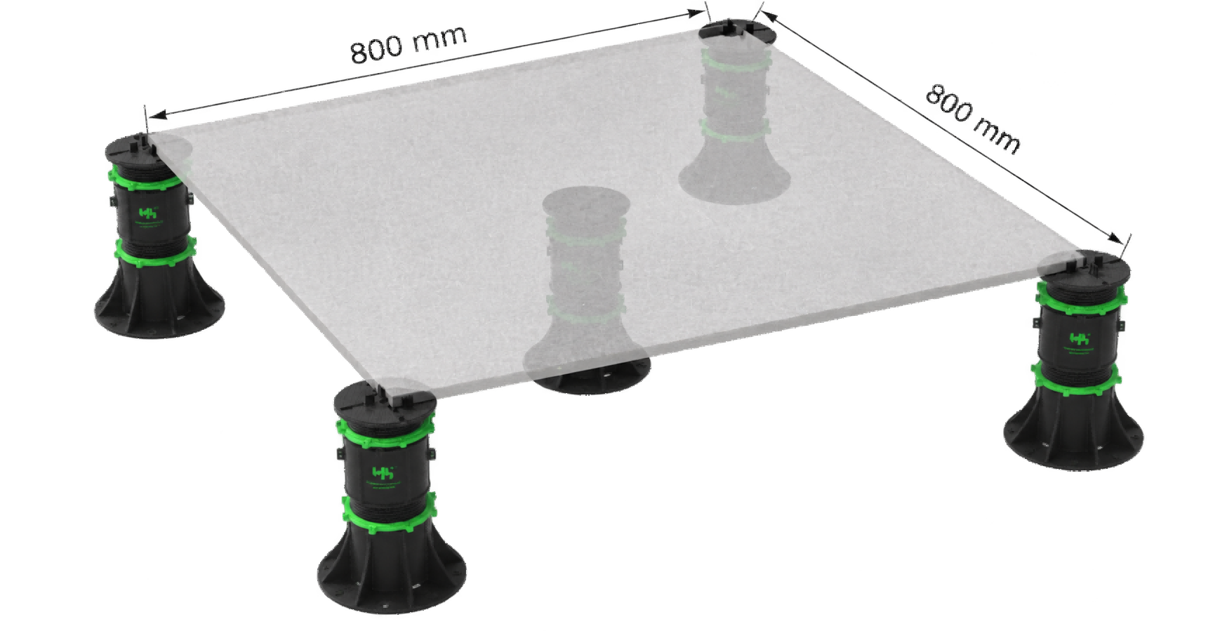
Structural Mechanics of Center Failure: 800 x 800 mm pavers provide clean, expansive architectural lines, but represent a severe mechanical hazard if under-engineered.
You MUST mandate a 5-point layout (4 corners + 1 central pedestal under the geometric center) for all 800 x 800 mm pavers!
1. Why 4-Corner Quotes from Competitors are Negligent: An 800 x 800 mm paver has a surface area of 0.64 m²—nearly 1.8 times larger than 600 x 600 mm. Under a 4-corner support layout, the unsupported center span is 800 mm (diagonal span ~1130 mm). When a dynamic point load (e.g., a person jumping with hard-soled boots or the narrow leg of a loaded cast-iron table) impacts the center, flexural tensile stress exceeds porcelain's modulus of rupture, causing sudden catastrophic brittle fracture (Punching Failure).
2. Correct Installation Sequence for Center Pedestals: The center pedestal must have its spacer tabs removed or be fitted with a smooth flat head. Affix a 2mm anti-vibration EPDM pad onto the head. First, level the paver accurately across the four corner pedestals. Then, rotate the central pedestal upwards until it contacts the underside of the paver with gentle pre-load tension. Never over-tighten, which would crown the paver.
2.5 600 x 1200 mm Format: 6-Point Support Protocol (4 Corners + 2 Long-Edge Midpoints)
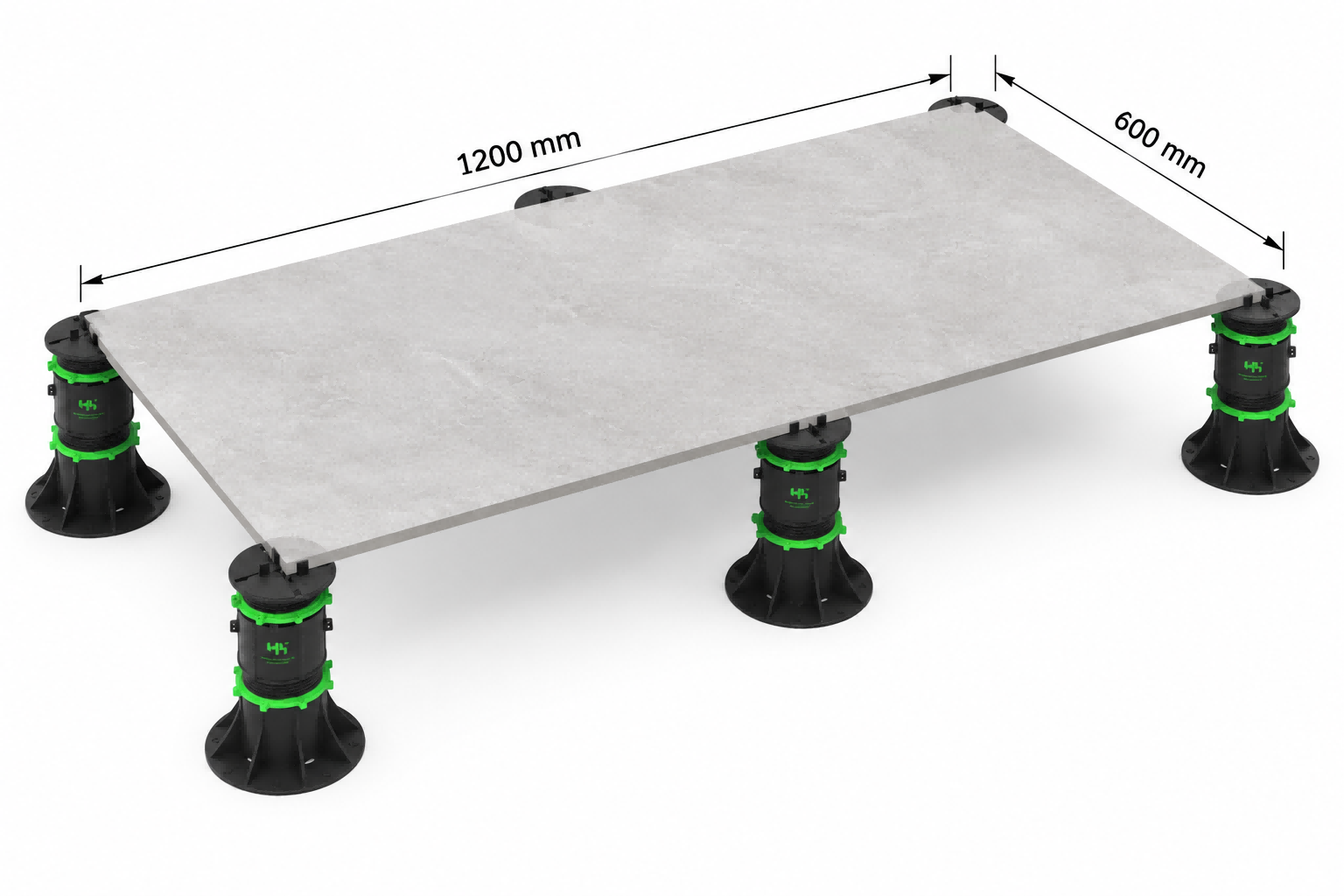
600 x 1200 mm slabs offer dramatic visual elongation, but exhibit severe structural asymmetry.
6-Point Support. Place 4 pedestals at the corners and 1 intermediate pedestal at the exact midpoint of each 1200 mm long edge.
The 1200 mm unsupported edge span exceeds the allowable safe bending limit of 20mm porcelain (standard unsupported limit is 700 mm). Stepping on an unsupported 1200 mm edge induces severe tensile stress, risking edge snapping. The dual midpoint supports divide the 1200 mm span into two safe 600 mm spans.
2.6 400 x 800 mm & 600 x 900 mm Rectangular Formats
For aligned grid layouts, reinforce long edges (>700 mm) with midpoint pedestals (6 points total). For staggered running bond (brick-pattern) layouts, paver ends meet the side centers of adjacent tiles, naturally doubling pedestal density. Sales engineers should calculate layout density from CAD drawings.
2.7 200 x 1200 mm / 300 x 1200 mm Plank Tiles: Critical Engineering Trap & Solution
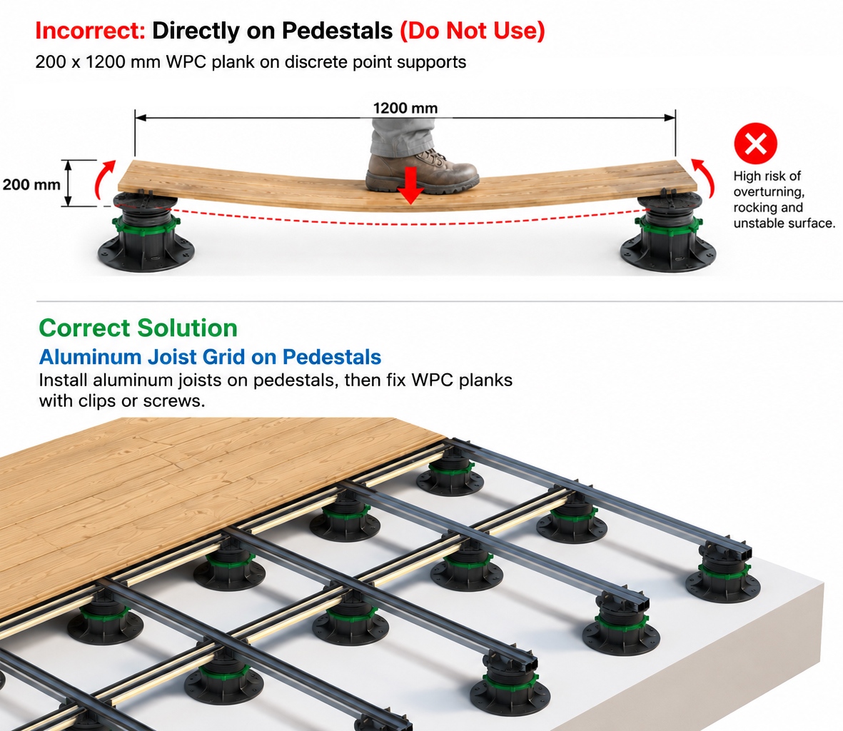
⚠️ Fatal Engineering Error: Clients frequently ask if wood-grain plank tiles (e.g., 200 x 1200 mm) can sit directly on pedestals. The answer is: ABSOLUTELY NEVER on discrete point supports alone!
Plank pavers have an extreme 1:6 aspect ratio. With a width of only 200 mm, stepping near long edges generates an aggressive overturning moment, causing pavers to tilt, rock, or dislodge—a major safety liability.
Solution 1 (Substructure Joist Grid): Erect an aluminum joist framework atop pedestals, then secure plank tiles to joists via clips or structural silicone.
Solution 2 (Integrated Paver Tray System): Place metal/polymer Paver Trays atop pedestals to form a continuous supportive deck, then seat plank pavers inside.
2.8 1200 x 1200 mm Formats: 9-Point Layout & Aluminum Sub-Frames
With a 1.44 m² surface area and heavy weight, install 9 pedestals per slab (4 corners + 4 edge midpoints + 1 center) or transition to an aluminum beam matrix.
SECTION 3: SUBSTRUCTURE JOIST SYSTEMS & SPAN SPECIFICATIONS FOR TIMBER/COMPOSITE DECKING
When elevating natural hardwood, thermo-treated pine, bamboo decking, or Wood-Plastic Composite (WPC) boards, pedestals support a sub-frame joist network rather than individual boards directly. Engineers and estimators must strictly separate two distinct span dimensions:
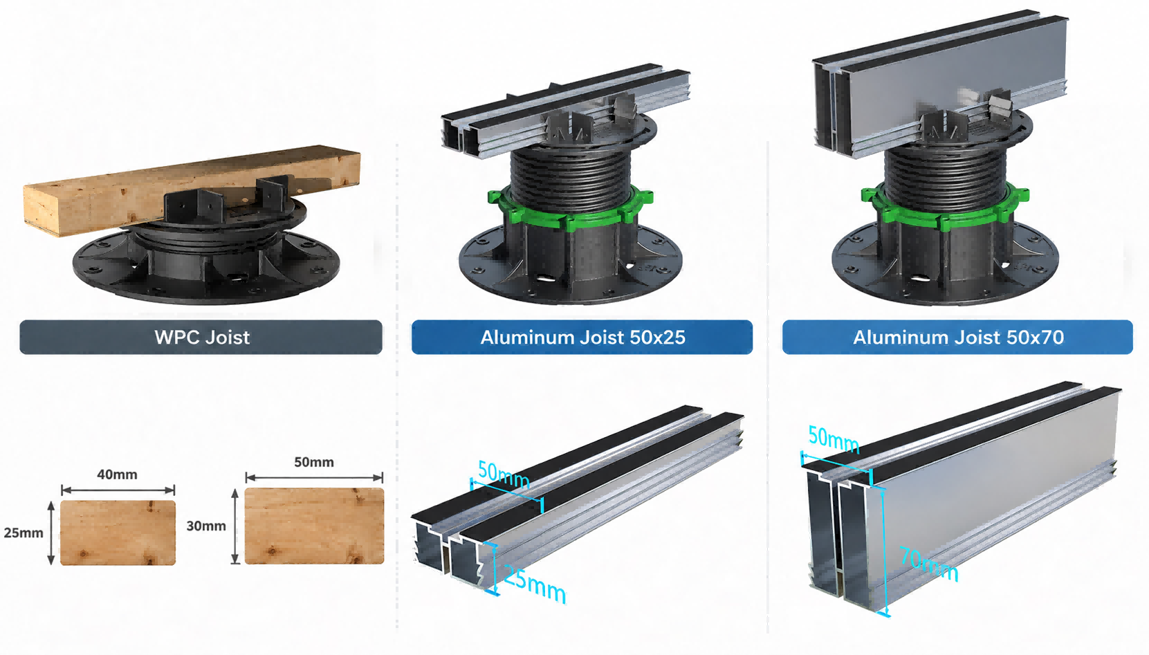
3.1 Wood-Plastic Composite Joists (WPC Joist / 40x25mm or 50x30mm)
Low modulus of elasticity and high thermal sensitivity. Polymer matrix undergoes viscoelastic creep under continuous dead load and solar exposure.
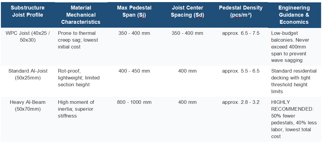
Both span directions must not exceed 400 mm! Pedestal spacing 350-400mm; parallel joist spacing 350-400mm.
Never expand pedestal spacing to 500 mm to cut costs. Under summer sun, composite joists will sag into a permanent wavy profile, provoking warranty claims.
3.2 50 x 25 mm Standard Low-Profile Aluminum Joist (1.5–2.0 mm Wall Thickness)
6063-T6 architectural alloy; rot-proof, lightweight, and zero moisture expansion. However, a 25 mm profile height provides limited flexural rigidity.
Pedestal spacing 400mm; joist spacing 400mm.
Ideal for low-clearance residential balconies and refurbishment projects with tight finish heights.
3.3 50 x 70 mm Heavy-Duty Deep-Section Aluminum Joist (High-Span Beam)
With a 70 mm profile depth, the sectional moment of inertia is over 4 times greater than a 50 x 25 mm joist, dramatically enhancing bending resistance.
Pedestal spacing expands to 700 mm – 800 mm! Parallel joist spacing remains 400 mm (dictated by decking board flexure).
3.4 Joist Cradles & Thermal Expansion Gap Provisions
Pedestals must be equipped with specialized joist cradles with lateral locking tabs. Aluminum joists must be secured through side pre-punched holes with stainless-steel self-drilling screws. Joist butt joints must incorporate a 5–10 mm expansion gap to absorb thermal expansion cycles.
SECTION 4: PROJECT APPLICATION SCENARIOS & ENGINEERING SAFEGUARDS
4.1 Roof Terraces & Green Roof Podiums
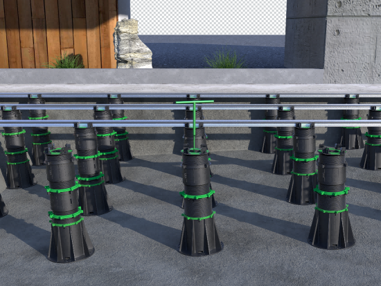
• Membrane Protection: Broad pedestal base plates with chamfered bottom rims distribute point loads. Specify 200x200x2mm anti-punching recycled rubber protection mats beneath every base.
• Slope Correction: Structural slabs typically slope 1%–3% for drainage. Fit 0–5% base/head slope correctors or self-leveling heads to establish an absolute level surface.
• Wind Uplift Mitigation: In high-wind and coastal zones, integrate perimeter locking clips or Paver Tray sub-deck systems to mechanically lock pavers into a unified wind-resistant diaphragm.
4.2 Low-Profile Thresholds & Balcony Retrofits
• Challenge: Refurbishments often present mere 20–30 mm finished floor clearances beneath sliding door weep holes.
• Solution: Deploy Mini Ultra-Low Pedestals (10–17mm / 17–25mm / 19–30mm) combined with 2mm acoustic shims, preventing door obstruction.
4.3 Water Features, Reflection Pools & Fountains
• Hydrolysis & UV Resistance: Fabricate exclusively from UV-stabilized polypropylene (PP). Prohibit cheap mineral-filled re-grind plastics that swell or degrade when submerged.
• Hydraulic Flow Channels: Pedestal bases must incorporate multi-directional perforations to allow continuous water circulation, preventing dead-water bacterial colonization.
4.4 High-Traffic Commercial Plazas & Public Conspaces
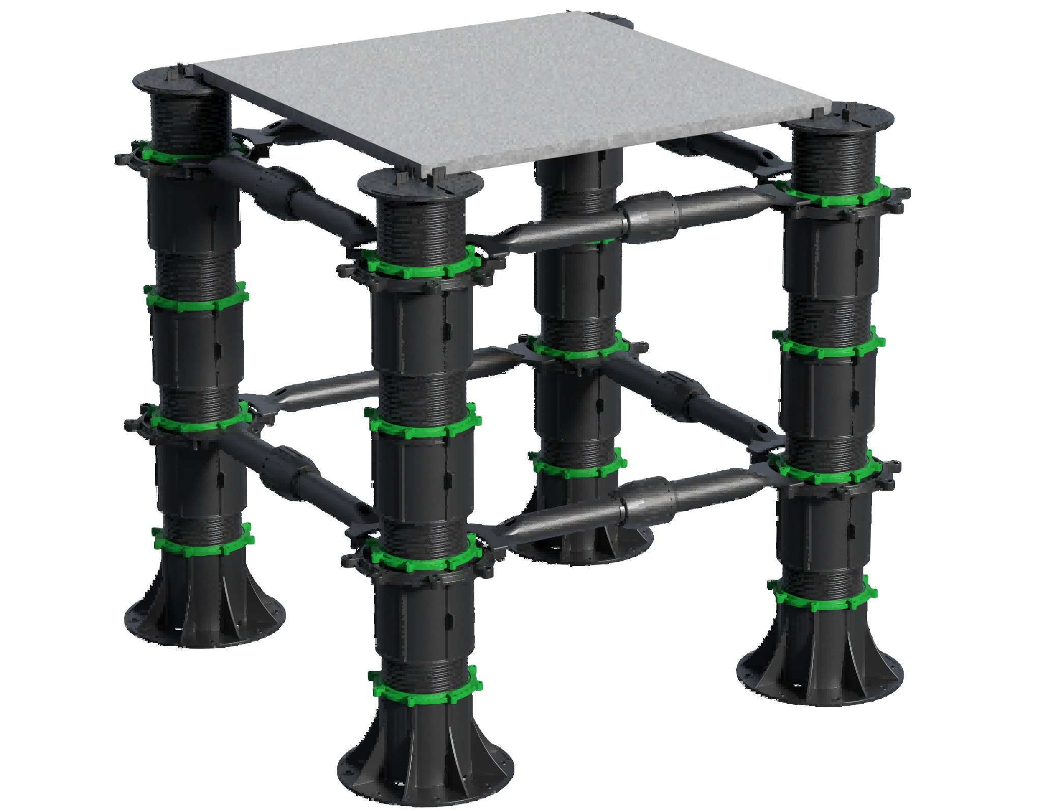
• Static & Dynamic Load Requirements: Pedestals must withstand certified crushing loads >= 1,200–1,500 kg (EN 12825 Class 6).
• Cross-Bracing Truss System: When cavity elevation exceeds 600 mm, lateral shear moments escalate. Clamp collars to pedestal stems and lock diagonal bracing rods between adjacent pedestals, establishing a rigid 3D truss.
SECTION 5: PRECISE MATERIAL CALCULATION FORMULAS & RULE-OF-THUMB ESTIMATION
5.1 Quick Estimating Multipliers (Rule of Thumb)
• 300 x 300 mm Pavers: 11.0 - 12.0 units / m² (Mini Pedestals mandatory)
• 400 x 400 mm Pavers: 6.5 - 7.5 units / m²
• 600 x 600 mm Pavers: 2.8 - 3.2 units / m²
• 800 x 800 mm Pavers: 3.2 - 3.8 units / m² (including 5th center pedestal)
• 600 x 1200 mm Pavers: 2.8 - 3.5 units / m² (including dual long-edge midpoints)
• Decking on 50x25mm Al-Joists: 5.5 - 6.5 units / m² (Sj=400mm, Sd=400mm)
• Decking on 50x70mm Heavy Al-Beams: 2.8 - 3.2 units / m² (Sj=800mm, Sd=400mm - 50% Fewer Pedestals!)


Mobile/WhatsApp:+ 86 176 8231 3725
ADD:Room B205, Cross-Border E-Commerce Comprehensive Pilot Area, No. 776 Jianshe 1st Road, Xiaoshan District, Hangzhou Zhejiang, China


Copyright: Hangzhou Moonbay Industrial Co., Ltd. @ 2021 record Technical support: xuanmeng network
 Home
Home

